
Despite the dominance of full-color OLED and IPS displays in modern smartphones and laptops, the monochrome LCD (Liquid Crystal Display) remains one of the most widely manufactured display technologies on the planet in 2026. From digital watches and industrial meters to medical devices and embedded systems, monochrome LCDs continue to power billions of devices where simplicity, ultra-low power consumption, and sunlight readability outweigh the need for vivid color. This technical deep dive explores exactly how monochrome LCDs work at the physical, chemical, and electrical level.
For the latest display technology comparisons and mobile phone specifications, explore MobileKiShop.
The Physics of Liquid Crystals
Liquid crystals are a unique state of matter that exists between a conventional liquid and a solid crystal. The molecules in a liquid crystal phase possess orientational order (they tend to align along a common axis called the "director") but lack the full positional order of a true crystal lattice. This anisotropic molecular alignment is the fundamental property that makes LCD technology possible.
Nematic Phase and the Director Field
Monochrome LCDs almost exclusively use nematic liquid crystals, where rod-shaped molecules (typically cyanobiphenyls like 5CB or 8OCB) align roughly parallel to one another. The average direction of alignment is described by a unit vector called the director (n). The key engineering insight is that the orientation of the director can be controlled by external electric fields because the molecules have a permanent or induced dipole moment. When voltage is applied across a thin layer of nematic LC, the director field reorients, which in turn changes how polarized light passes through the material.
Monochrome LCD Panel Architecture: Layer by Layer
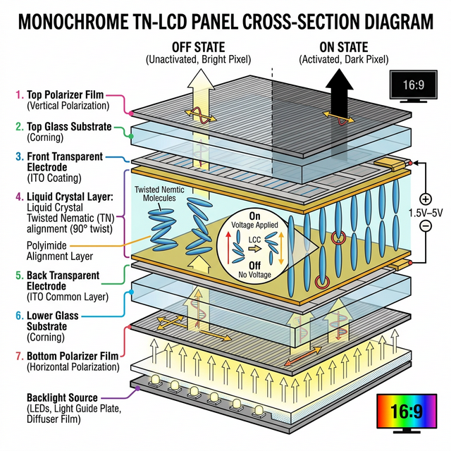
A standard monochrome LCD panel is a sandwich of precisely engineered layers. Understanding each layer is critical to grasping how monochrome displays create visible contrast.
1. Polarizer Films
Two linear polarizer films are placed on the outermost surfaces of the panel, oriented at 90 degrees to each other (crossed polarizers). Without any liquid crystal between them, no light can pass through this arrangement. The polarizers are typically made from stretched polyvinyl alcohol (PVA) film impregnated with iodine, laminated onto protective triacetyl cellulose (TAC) substrates.
2. Glass Substrates and ITO Electrodes
Two thin glass substrates (typically 0.5mm to 1.1mm soda-lime glass) form the structural backbone. On the inner surface of each glass, a transparent conductive layer of Indium Tin Oxide (ITO) is sputtered to a thickness of approximately 100-200 nanometers. ITO provides the electrical contacts needed to apply voltage across the liquid crystal layer while maintaining over 85% optical transparency in the visible spectrum.
3. Alignment Layers
A thin polyimide (PI) layer (approximately 50-100nm) is deposited on top of each ITO electrode and then mechanically rubbed in a single direction using a velvet-wrapped roller. This rubbing process creates nanoscale grooves that force adjacent liquid crystal molecules to align along the rubbing direction. The two alignment layers are oriented 90 degrees apart, which creates the critical twisted nematic (TN) configuration when the cell is assembled.
4. Liquid Crystal Layer
The gap between the two glass substrates (the "cell gap") is maintained at a precise distance of 4 to 8 micrometers using glass or polymer spacer beads. This gap is filled with nematic liquid crystal material. In the relaxed (no voltage) state, the molecules form a continuous 90-degree twist from one substrate to the other, acting as an optical waveguide that rotates the polarization of incoming light by exactly 90 degrees.
5. Backlight or Reflector
Depending on the display type, a backlight module (LED edge-lit or direct-lit) provides illumination from behind (transmissive mode), a metallic reflector bounces ambient light back through the panel (reflective mode), or a transflective layer combines both approaches for indoor/outdoor versatility.
The Twisted Nematic (TN) Effect: How Pixels Turn On and Off
The core operating principle of a monochrome TN-LCD is elegantly simple:
- Voltage OFF (Bright State): The 90-degree molecular twist rotates the polarization plane of incoming linearly polarized light by 90 degrees. This rotated light now aligns with the second (crossed) polarizer and passes through. The pixel appears bright or transparent.
- Voltage ON (Dark State): An AC voltage (typically 3V to 5V RMS at 30-100 Hz) is applied across the ITO electrodes. The resulting electric field overcomes the elastic restoring torque of the liquid crystal, causing the molecules to untwist and align perpendicular to the substrates (homeotropic alignment). In this state, no polarization rotation occurs, and the light is blocked by the crossed polarizer. The pixel appears dark.
The threshold voltage (Vth) at which the molecules begin to tilt is governed by the Freedericksz transition and is typically between 1.5V and 2.5V for common TN mixtures. The response time (the time to switch from bright to dark and back) ranges from 15ms to 50ms for standard monochrome panels, which is more than adequate for static text and simple animations but insufficient for video-rate content.
Driving Methods and Controller ICs
Direct Drive (Static)
For simple displays with a small number of segments (such as a 7-segment digit), each segment has a dedicated electrical connection to the driver IC. This is called static drive and offers the highest contrast ratio and simplest timing because each segment is independently addressed at all times. The drawback is pin count: an N-segment display requires N+1 connections (N segments plus one common backplane).
Multiplexed Drive
For larger displays (character modules, graphic dot-matrix panels), multiplexing is essential. In a multiplexed scheme, rows (commons) and columns (segments) share electrical lines. The driver scans one row at a time, applying the correct column voltages for that row before moving to the next. A 128x64 graphic LCD, for example, might use a 1/64 duty cycle multiplex, meaning each row is actively driven for only 1/64th of the total frame time.
The key challenge in multiplexing is maintaining adequate contrast ratio. Because non-selected pixels still receive a partial voltage (the "cross-talk" or "ghosting" voltage), there is an inherent trade-off governed by the Alt and Pleshko selection ratio:
Von / Voff = sqrt((N + 1) / (N - 1))
where N is the number of multiplexed rows. As N increases, the ratio approaches 1, meaning on and off pixels become nearly indistinguishable. Super Twisted Nematic (STN) cells with 240-270 degree twist angles were developed specifically to sharpen this voltage-transmittance curve and enable higher multiplex ratios (up to 1/240 duty).
Common Driver ICs
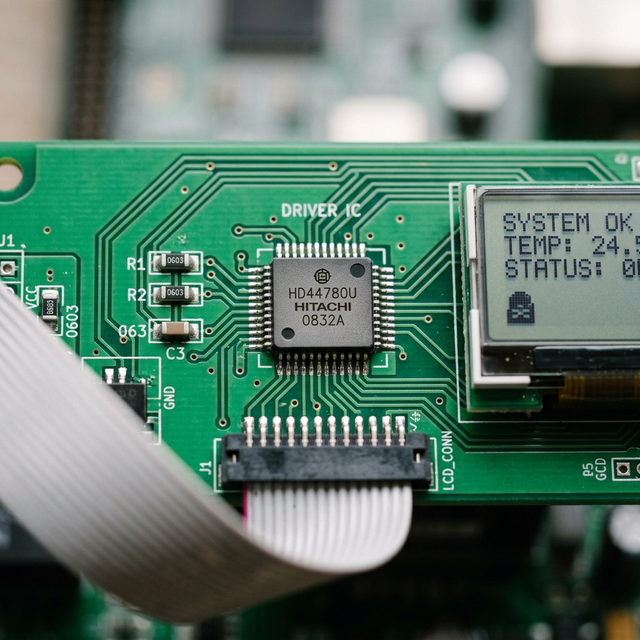
Popular monochrome LCD controller/driver ICs in 2026 include the HD44780 (the legendary Hitachi character LCD controller, now manufactured by dozens of licensees), the ST7920 (128x64 graphic with Chinese character ROM), the SSD1306 (technically an OLED driver but widely used), and the UC1701 for ultra-low-power COG (Chip-on-Glass) modules. Communication interfaces range from parallel 4/8-bit buses to SPI and I2C serial protocols.
Display Mode Variants: STN, FSTN, DSTN, and HTN
While TN is the foundational technology, several important variants exist for monochrome applications:
- STN (Super Twisted Nematic): Uses a 180-270 degree twist angle instead of 90 degrees. This produces a much steeper electro-optic response curve, enabling higher multiplex ratios. The trade-off is a characteristic blue-green or yellow-green color tint due to wavelength-dependent birefringence.
- FSTN (Film-compensated STN): Adds an optical retardation film to the STN panel to neutralize the color tint, producing a clean black-on-white or white-on-black appearance. This is the most popular choice for high-quality monochrome graphic displays.
- DSTN (Double-layer STN): Uses two STN cells stacked together to cancel the birefringence color. Largely superseded by FSTN due to cost and thickness considerations.
- HTN (High Twisted Nematic): A compromise between TN (90 degrees) and STN (180+ degrees), typically using a 100-120 degree twist. Offers better contrast than TN with faster response times than STN.
Modern Applications of Monochrome LCDs in 2026
Despite being one of the oldest active display technologies, monochrome LCDs remain irreplaceable in several critical sectors:
- Medical Devices: Blood glucose meters, pulse oximeters, blood pressure monitors, and infusion pumps rely on monochrome LCDs for their ultra-low power draw (enabling years of battery life on a coin cell), excellent sunlight readability, and wide operating temperature range (-20C to +70C).
- Industrial Instrumentation: Digital multimeters, oscilloscope status displays, PLC (Programmable Logic Controller) HMI panels, and environmental sensors use monochrome character and graphic LCDs for harsh-environment reliability.
- Consumer Electronics: Calculators, digital watches, kitchen appliances (microwave timers, oven displays), and fitness trackers continue to use monochrome LCDs where color is unnecessary, and battery life is paramount.
- Automotive: Instrument cluster secondary displays, tire pressure monitoring systems (TPMS), and aftermarket OBD-II scanners commonly use monochrome character LCDs for cost-effective, reliable data presentation.
- IoT and Embedded Systems: In the rapidly growing Internet of Things space, monochrome graphic LCDs (often 128x64 FSTN panels driven via SPI) are the go-to choice for sensor nodes, smart home controllers, and edge computing devices where every microamp counts. For deeper insights into how mobile devices connect to IoT ecosystems, check our tech blog.
Power Consumption: Monochrome LCD vs. Color Technologies
One of the most compelling technical arguments for monochrome LCDs is their extraordinary power efficiency:
| Technology | Typical Power (3-inch equivalent) | Backlight Required? |
|---|---|---|
| Reflective Monochrome LCD (TN/STN) | 5-15 uW (no backlight) | No (uses ambient light) |
| Transflective Monochrome LCD | 10-50 mW (with LED backlight) | Optional |
| Color TFT-LCD (IPS) | 150-400 mW | Yes (always) |
| OLED/AMOLED | 100-350 mW (content dependent) | No (self-emissive) |
A reflective monochrome LCD consumes roughly 10,000 to 25,000 times less power than a color TFT-LCD of similar size. This is why a basic digital watch can run for 5-10 years on a single CR2032 coin cell battery. The liquid crystal material itself consumes virtually zero DC power; the only energy cost is the AC excitation signal and driver IC logic, which is measured in microwatts. Compare this to the display specifications of modern smartphones which consume hundreds of milliwatts on their screens alone.
The Future of Monochrome LCDs
Far from being obsolete, monochrome LCD technology continues to evolve. Recent developments in 2026 include memory-in-pixel (MIP) monochrome LCDs that hold their image without continuous refresh (reducing power to near-zero during static display), and flexible monochrome LCD panels printed on polymer substrates for wearable and curved-surface applications. The global monochrome LCD market is projected to remain robust through the decade, driven by IoT expansion, medical device miniaturization, and the relentless demand for ultra-low-power embedded displays.
For comparisons between different display technologies across the latest Android and iOS devices, explore MobileKiShop.